First pass at a precision multislope ADC
A multislope ADC is built around an integrating op-amp. A runup phase integrates the input signal for a fixed count. The input is then switched to a known reference voltage for a run-down phase.
The measurement is derived from the clock count at the time of a zero-crossing. Because the two phases work in opposite directions, component parasitics cancel to produce very accurate measurements.
Multi-slope ADC advantages
- can be made from a few simple components
- very high-precision and proven design choice for 6.5 digit plus DMMs.
- can measure both +ve and -ve with the addition of an inverted reference and extra software logic.
- The reset which is performed by shorting the integration capacitaor automatically adjusts and compensates the op-amp input voltage offset. This is similar in to same the way that a chopper op-amp auto-adjusts.
- controllable integration period. for example set as a multiple of 50/60Hz to control for line noise
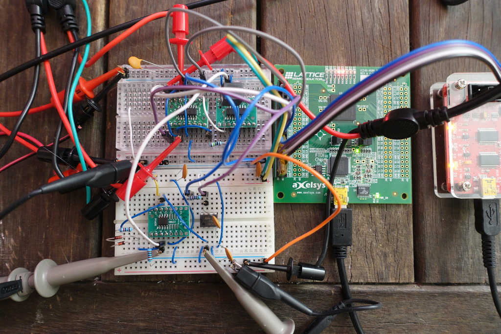
Design Prototype
The prototype circuit uses a dg444 multiplexor to switch inputs to the integrator which is based on a lf411 jfet type op-amp. Digital control of the multiplexor is handled by a Lattice ice40 fpga.
Communication with the fpga is over SPI, and a bus-pirate is handles the USB to SPI to allow communication with a laptop. The fpga acts as SPI slave and implements the clock-domain crossing logic written in verilog.
The verilog code for the fpga is synthesized using the excellent open-source Icestorm tools.
Breadboard
The initial breadboard design used a ceramic capacitor for the integrator. Taking a few measurements however showed a lot of variation. Replacing the cermic with a polypropelene type with low dielectric absorption greatly improved stability.
The comparator circuit used to detect the zero cross is also based on a lf411 - with a common-emitter bjt using a collector pull-up to handle 3.3V voltage conversion to interface to the fpga I/O.
Verilog
Verilog test code for the integration sequence looks like this,
    begin
        // increment clock
        count <= count + 1;

        // start integration
        if(count == reset_count)
            m_reset <= 1'b1;   // clear reset to begin runup

        // finish runup
        else if(count == runup_count)
            m_in <= 1'b1;       // swap to reference input for rundown

        // finish rundown
        if(zerocross_down)
        begin
            // we're done, so record count...
            integration_count <= count - reset_count;
            // and reset line values
            m_reset <= 0;
            m_in <= 0;       // for 5V
        end
    end
Issues
The scope view (time division 100uS) shows the final stage 2n3904 bjt (yellow trace) level-shifter switches very quickly. However the lf411 configured as the comparator (blue trace) has an output that swings very slowly.

Since the voltage slew is well under the capabibility of the of the lf411, it is probable that the open-loop gain is too low to accurately detect the zero-crossing when very small voltage differences are involved.
A faster decompensated op-amp should help here. There is probably no need for a very-high input impedance type, since the signal is current buffered by the integrating op-amp. This makes it possible to use an op-amp with a bipolar front end.
The op-amp also needs to have a good tempco to generate stable results.
Also the dg444 only measures 1M ohm resistance on an off channel - when measuered with a multimeter. Perhaps an issue of dg444 leakage from the current that the multimeter generates for performing ohms measurement?