Keithley 2420 SourceMeter Repair
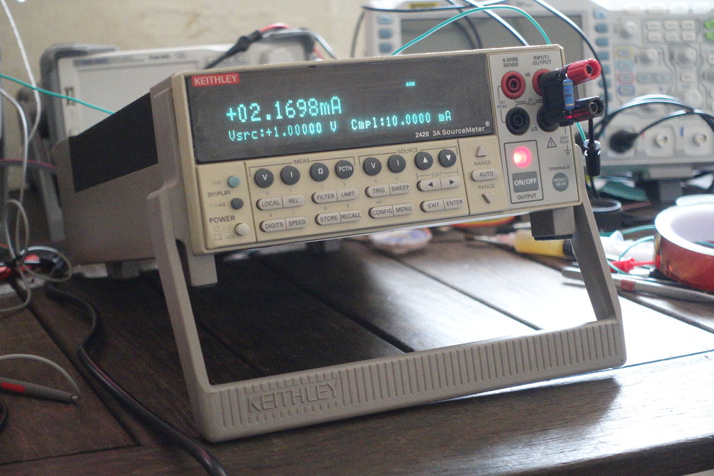
The Keithley 2400 line of SourceMeters combine three instruments in one 1,
- A fast and precise 6.5 digit DMM, with ability to measure voltages, currents and resistance.
- A precision power source, with adjustable compliance levels (limits) for both voltage and current.
- And since it’s four-quadrant power unit, it can not only source but also sink current, acting as active load.
The SourceMeter was purchased, “for parts or not working”. An attached service note mentions a burned main powerboard and warns not to plug the unit in.
First observations
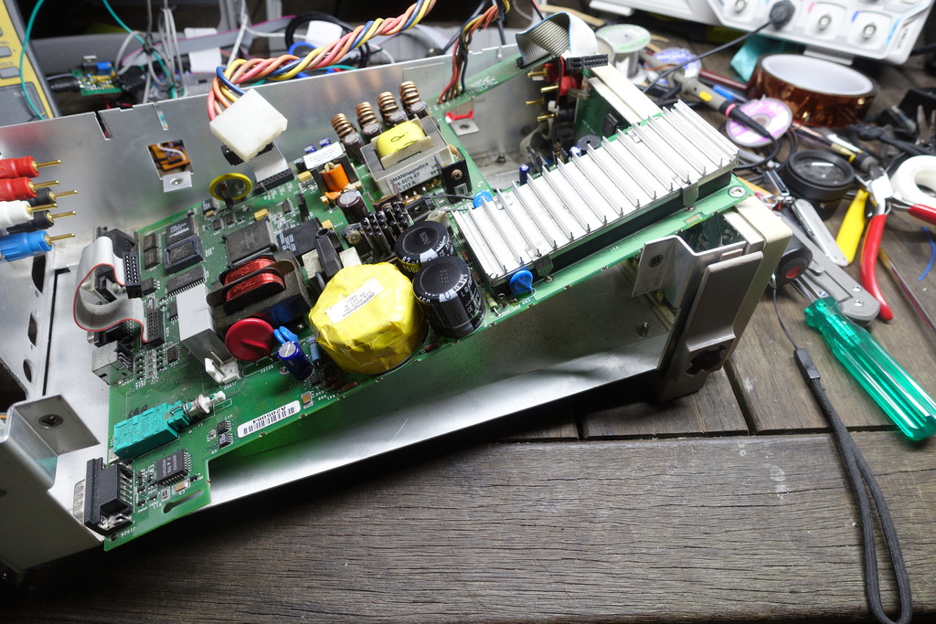
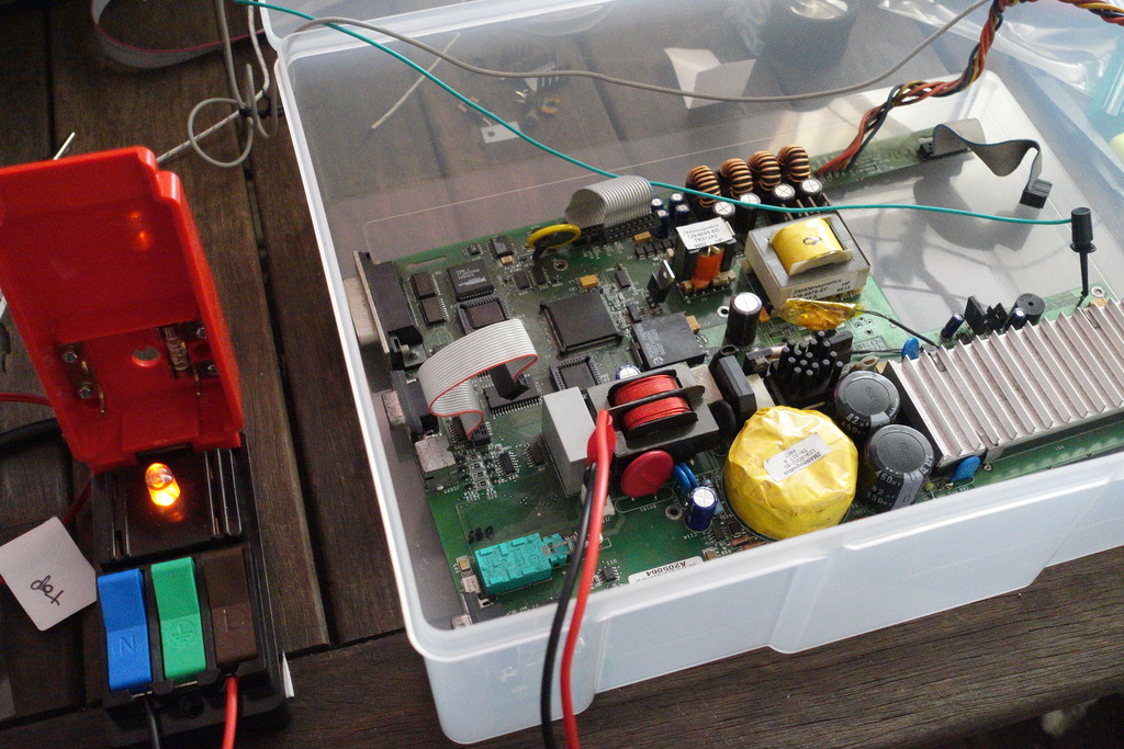
The instrument is easily dissassembled by removing of a few strategic chassis bolts. The interal layout is clean and well organised, and there is plenty of quality alumnium case-work.
Both top analog and lower digital/power boards appear to be in good general condition.

There are no bulging electrolytics, no burnt tantalums, and no signs of capacitor PCB leakage.
The main 3.15A (slowblo) fuse is intact and the CMOS battery shows 3V.
Access to the lower power-board is obtained after removing the upper board consisting of the analog and output sections.
Power supplies
The first surprise is that the power supply board is integrated with the digital board and is an obvious Keithley design.
A teardown of the lower output-current KEI2400 reveals the power supply of that instrument is a third-party component and quite independent of the digital board.
The power supply board is complicated by the many rail voltages it provides.
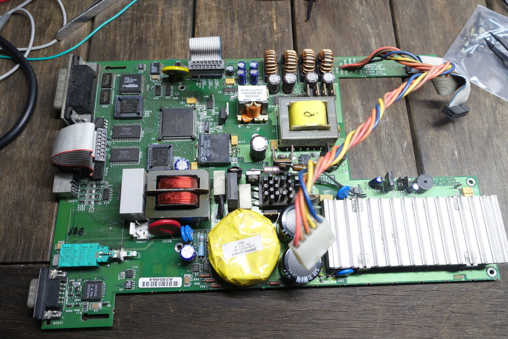
After analysing the components and service-manual, the supplies appear to include,
- mains to 24V SMPS
- 24 to 5V switchmode for digital power - a PowerTrends 78ST105SC
- a 12V linear regulator - a 7812 - for other digital IO, rs232, as well as mosfet driver for the main DC-DC converter
- A push-pull SMPS DC-DC converter with 24V complementary primaries and floating secondaries for 24 to +43, -43, +85, -85 for the output section
- a second DC-DC transformer hung off the first DC-DC transformer with floating +18, -18, +8 secondaries for the analog section
24V DC-DC push-pull converter
I suspect the main DC-DC converter that powers the analog and output sections is a push-pull SMPS for the following reasons,
- There is no identifiable negative feedback trace/opto-coupler from the secondary side. And no sophisticated regulator IC present. While push-pull designs lend themselves to to simple self-oscillation.
- Both the n-channel mosfets have their sources tied to common gnd implying that each drain is driving a different winding tap. For a dual mosfet with single winding primary we would expect the source and drain of two transistors to be tied and driving one side of a coil.
- The transformer has two main primaries and the inductances (measured in-circuit with an LCR meter) are symmetrical.
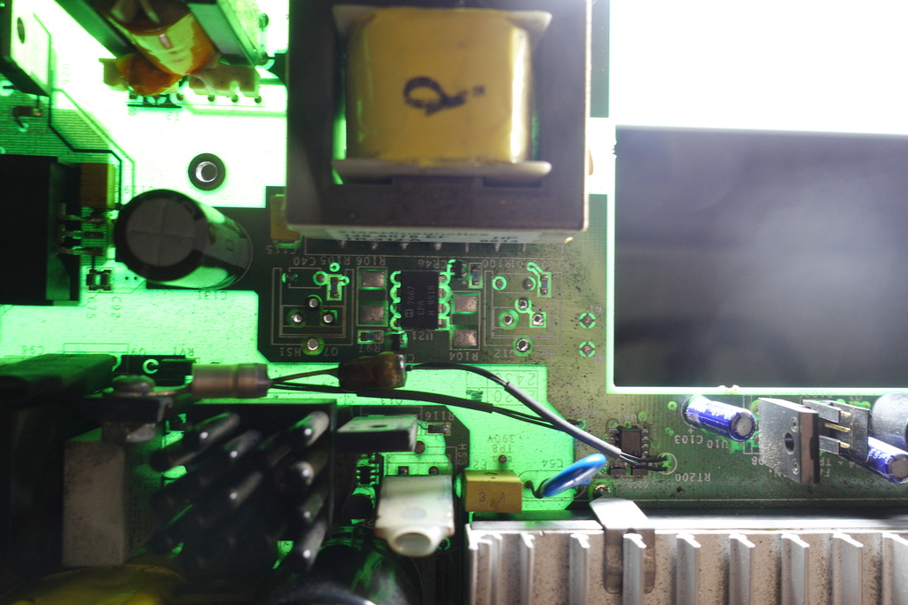
DC-DC Converter mosfet issues
Inspecting the mosfets that drive the DC-DC converter reveal a bunch of problems,
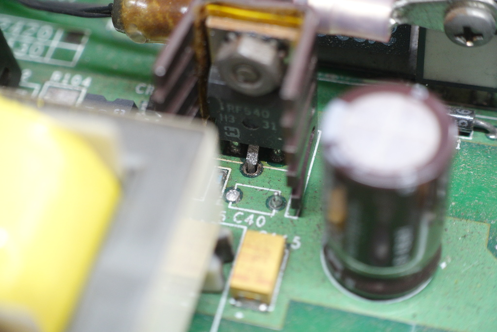
The via is missing - and there is no solder on the transistor leg. The heatsink mounting bolts are loose, and the thermistor insulator is discolored and melted. Also, the heatsink and bolts show some surface rust - perhaps due to extra heating/cooling stress.
So, I suspect that the mosfets have over-heated.
After turning the PCB upside down, there is evidence of a prior repair attempt. There is a bodge wire connecting another pcb pad to the transistor leg, and another one to the gate - which is odd because the gate via continuity tests OK.
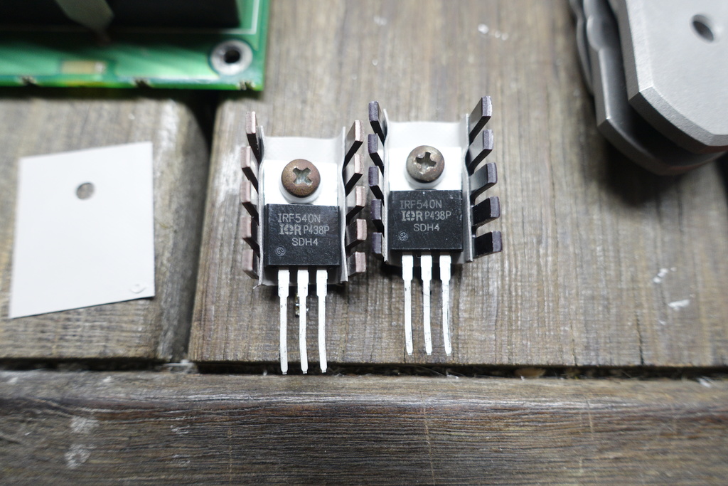
The IRF540 are likely replacements for the orignal mosfets which are listed in the service manual as IRFZ346. Google doesn’t seem to find the part-number. The service-manual lists another IRFZ346 and the corresponding part on the board is a IRFZ46N suggesting that the service manual part-number is a typo.
When tested in circuit the mosfets have a diode drop of 0.28V, but when pulled from the circut they test OK - at least according to a transistor-tester. Whatever their apparent condition - they will be replaced.
Removing the mosfets, and examining them closely also reveals that the heatsink plastic inserts have partly melted. That might explain why the heatsink bolts are not properly tensioned.
One of the mosfet’s heatsink insulation - a combination of silicon and kapton tape around the edges to protect from the wrap-around heatsink has been poorly implemented. There is some continuity between the to-220 package and the heatsink - which is soldered directly to PCB gnd.
Reverse engineering the traces between mosfets and switching transformer
Given the broken/missing via it is important to figure out the surrounding pad connections - so that alternative connections can be established.
This is difficult because of top and bottom layer copper fills that obscure the inner traces.
Trying to figure out the traces by testing pcb pad resistances is not sufficient because of all the low-resistance transformer taps that connect everything.
I ended up probing with an LCR meter - to identify suitable pads for connecting the mosfet drains to what I believed would be the correct primary coil taps over a low-inductance path - and not just indirectly via a low-resistance coil winding.
Powering the power board
With the DC-DC converter mosfets still removed and the downstream circuits (the two transformers) isolated - I tried powering the board for the first time.
The main SMPS 24V rail came up. Also the 5V SMPS and the 12V linear supply. The MCU buzzer emits a healthy beep!
Replacing the mosfets and heating problems
New IRF540s are prepared by mounting them to the heatsinks using over-sized to-247 silicone insulators to ensure isolation. The IRF540 differ from the original part type, but they should be OK given their high voltage and current rating.
The bodge work from the previous repair attempt is removed, and new drain connections established to make up for the missing vias.
Some thermocouples are glued to the to-220 packages to monitor temperature.
After applying power, the DC-DC converter appears to be working and the output section and analog board show voltages at the test-point pads.
Unfortunately, the mosfets are quickly overheating.
It takes just 30 seconds to rise to 140C (IRF540 max operating temp is 175C) with no load on the SM transformer.
Additionally the main 24V rail which was previously stable - is now unstable and intermittently drops out to 14V.
Gate drive and questions
Checking the circuit with a scope reveals the mosfets are getting poor gate-drive and spending most of their time in the linear region. They should be switching quickly to avoid resistive heating.
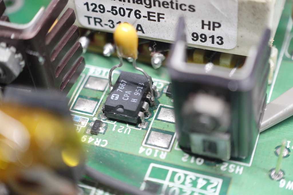
This is where the story becomes confusing. The push-pull mosfets are driven by a dual mosfet gate driver IC - to quickly charge and decharge the mosfet’s gate capacitance.
The service-manual specifies a TSC426 and the TSC426 datasheet states a 1.5A max current drive.
However the part found on the board is the pin-compatible ICL7667. The datasheet for the ICL7667 doesn’t state a max driving current, but a comment suggests the output section will draw up to 300mA.
So the fitted part is underpowered compared with the specified component!
Even more surprising, is that high-value gate resistors are fitted! The service manual states that R103 and R105 are 1k (confusingly the board ones measure 500ohm). So with 12V provided by the 7812, the gates would be getting only 12mA!
The questions are - who fitted the inferior ICL7667? And why design around an expensive and specialized mosfet gate driver in the first place - but then place high-value resistors after it (assuming it is not another service-manual typo) to limit current!
The TSC426 datasheet also specifies power requirements that include a higher valued decoupling cap - a 4.7uF in addition to a 0.1uF ceramic. However, testing the +ve and -ve pins of the driver with an LCR meter reveal only 0.5uF capacitance available from the populated PCB caps.
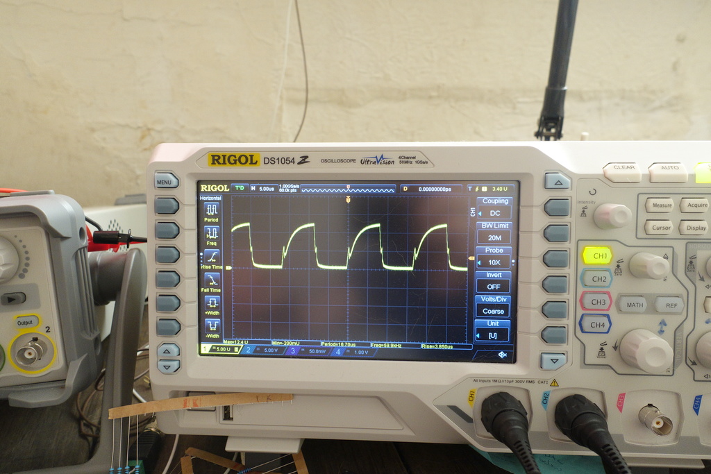
Experiment
As a simple experiment - I exchanged the resistors with 22ohm ones, and soldered a tantalum capacitor across the power pins of ICL7667.
The oscilloscope shows the improvement in gate switching,
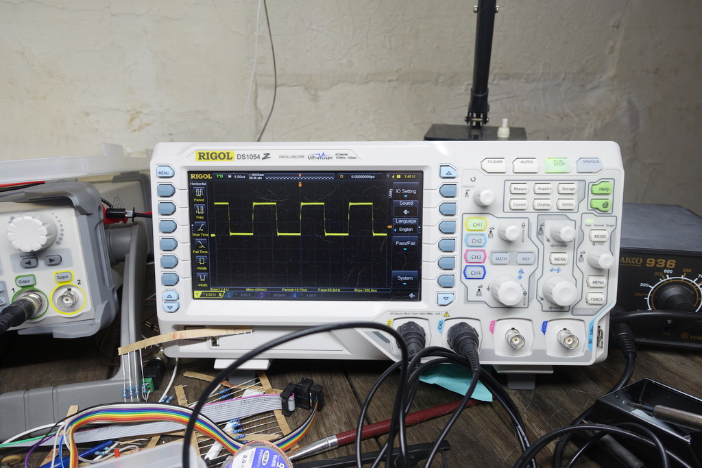
When the board is powered up again - the mosfets run without dramatic over-heating and using only passive cooling.
The 24V rail that was previously dropping out is also stable.
The mosfets are still hot with just passive cooling (around 100C) - but it is a step in the right direction.
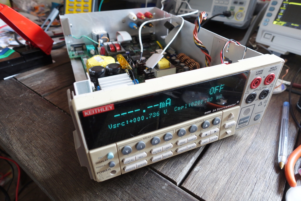
Apart from the board power supplies, I have no idea about the condition of the digital circuitry. After placing the board into the case enclosure and connecting the front-panel there are encouraging signs of life,
Active cooling
I decided it would be good to check what difference the fan would make and reconnected it.
Even without the the full case assembly to ensure ducted airflow, the fan is quite effective.
The first mosfet (closest to the fan) reads below 30C, and the second sits about 35C.
Until this point, I had wanted to revert to the original TSC426 to further improve gate-drive. However, noticed the ICL7667 chip had a datecode prior to the instrument’s manufacture date. That suggests Keithley are likely responsible for the substitution during manufacture.
With the improvements from lowering the gate resistor values, and from active cooling, I decide the temperatures are probably OK.
Time to reassemble everything.
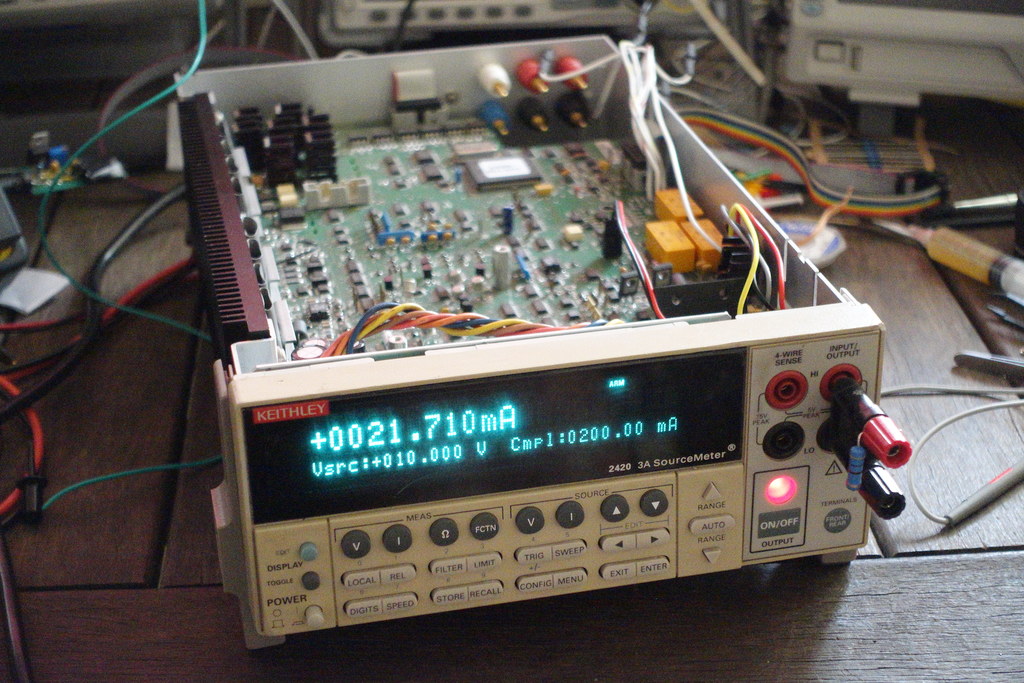
After chasing down an forgotten flex that had been overlooked, the SourceMeter is now capable of sourcing voltage again!
1 TiN from eevblog has a great description of the key features.