2DW23x Zeners (part 6)
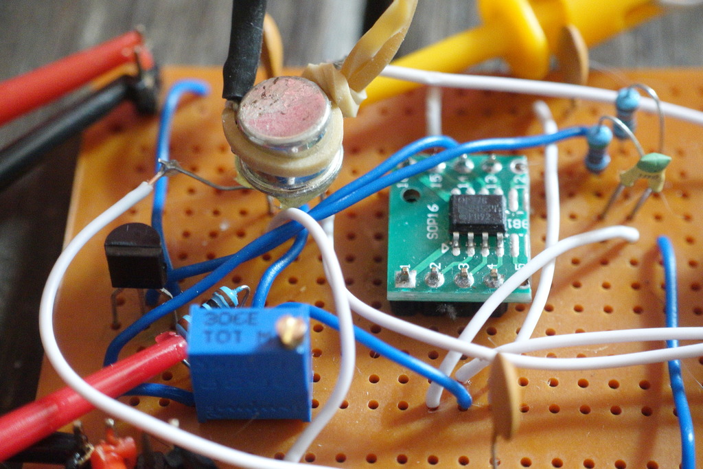
Removing the current adjust trimmer
Previous circuits employed a trimmer for adjusting zener current in order that TC0 can be set at a temperature that is convenient to regulate using the heater loop (eg. 10-20C above ambient).
Final adjustment involved changing the temperature set-point to align with TC0 given the zener current.
However, the following tests suggest it may be possible to eliminate the current adjustment trim altogether. Instead, we can rely on modulating the set-point temperature for the TC0 - provided the initial current is within a range suitable for regulation - and after accounting for component value tolerances.
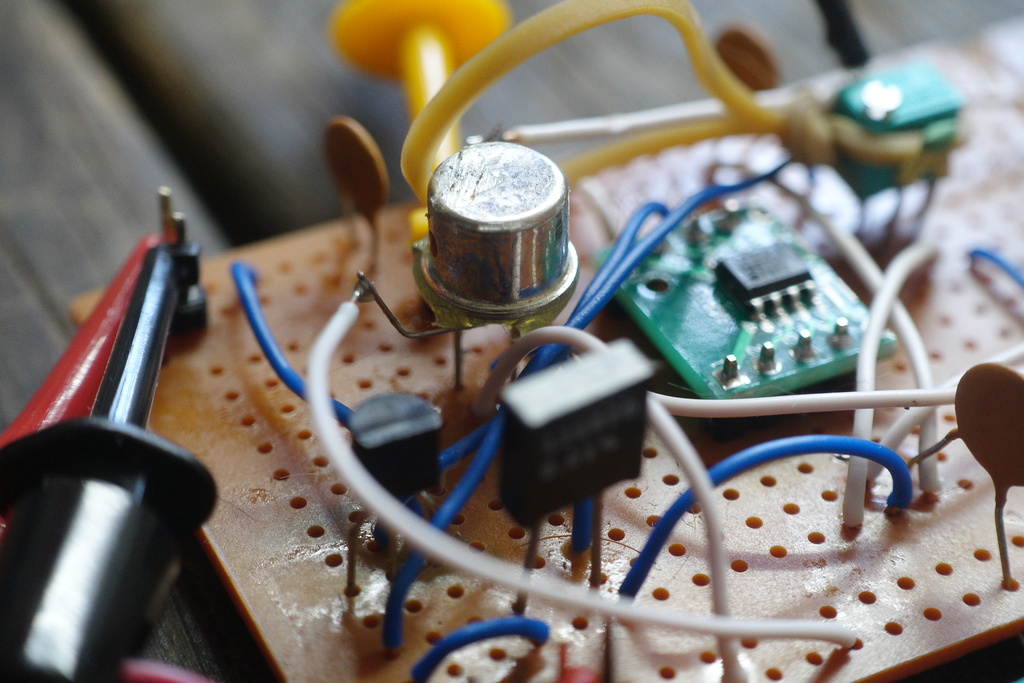
In the following tests, the high-side current trimmer was removed and replaced with fixed-resistor divider to set current via the inverting op-amp input.
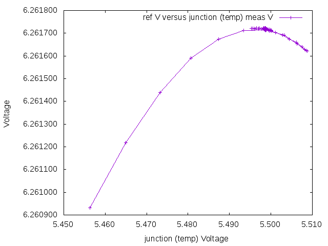
Using a 5.1/10k divider
A 5.1k/10k fixed-resistor divider is used to set the inverting op-amp voltage and indirectly the zener current. The ref voltage is 6.269V. When we perform a cold-start, the operating temperture appears too low and TC0 actually appears to be at a junction temp of around 5.20V (about 63C case-temp) given the zener current.
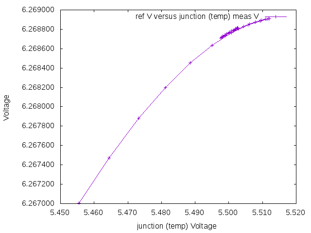
After adjusting the temperature set-point, another run confirms temperature is now regulated correctly at TC0.
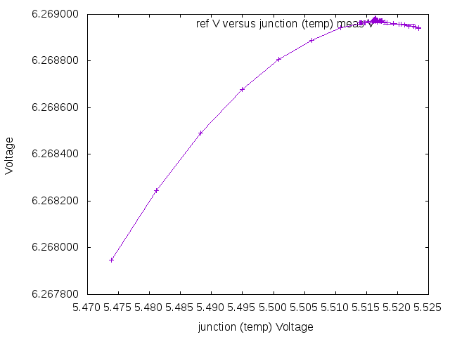
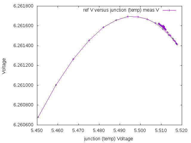
Using a 4.7/10k divider
We now swap the the divider to 4.7k/10k fixed-resistor divider.
This gives a ref voltage output of 6.261 - about 8mV lower - and a correspondly lower zener current.
The set temperature - still adjusted to 63C from the previous run looks too be too high for the TC0. Instead we need a junction temperature around 5.000V - or about 10C lower than before.
After adjusting the set-point temperature, everything is aligned again.
This demonstrates that any fixed divider pair - between 4.7/10k and 5.1/10k is suitable since we can adjust the set-point temperature to account for the change in TC0 for slightly different zener currents.