Zeners (part 4)
Testing trimpot temperature sensitivity
It would be desirable to confirm which components are responsible for the ambient temperature sensitivity observed in part-3.
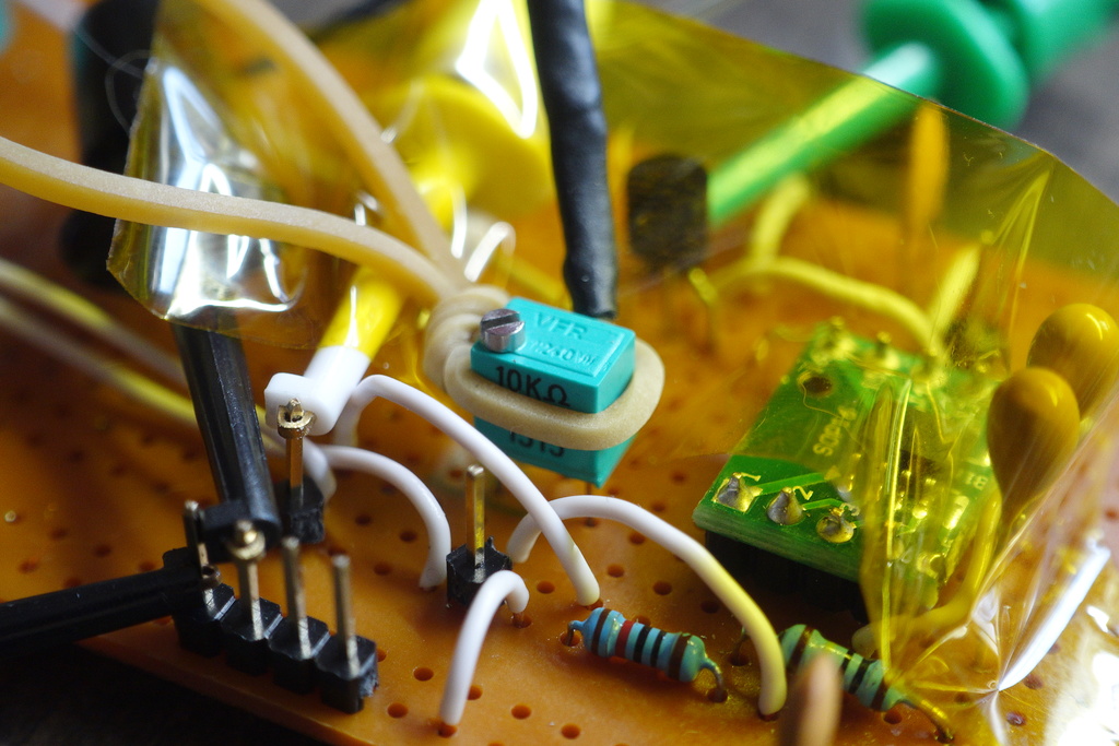
A heatgun provides a crude way to test the temperature sensitity of the trimpots used as dividers to set voltages for op-amp inputs.
Using the heatgun on lowest settings and a small nozzle attachment, hot-air is pointed at the trimpot for a 10C rise, and then pulled away to allow the component to cool. Kapton tape helps to shield heat away from board components that are not under test.
The measurements are derived from a K-thermocouple held against the backside of the trimpot case with a rubber-band. The measurement interval is 10 seconds.
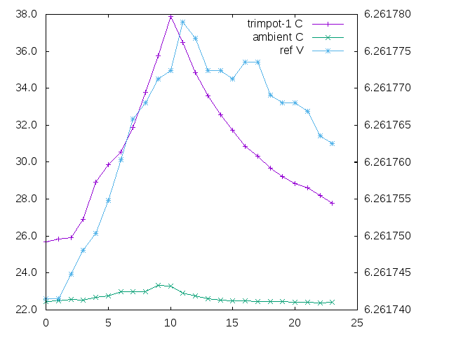
Current adjust trimpot
Plot showing the temperature rise and fall for the current adjustment trimpot, as well as the strong voltage-reference correlation. The plot reveals a 40uV swing over a 10C (26-36C) change in temperature - or about 4uV/C.
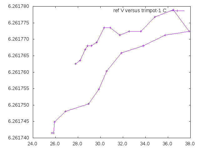
Plot of variables against each other
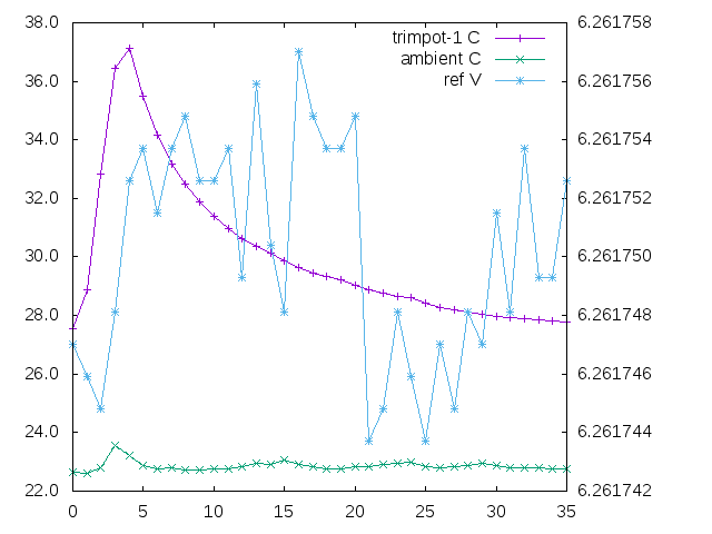
Temperature setpoint trimpot
Testing the temperature response of the second trimpot shows little identifiable affect on the reference voltage. Here, there is a 12uV swing, which is only a bit higher than the background noise readings. And there is no obvious correlation with temperature. Plots of junction temperature confirm the temperature regulation loop is less dependent on the trimpot tempco.
Other variation
Another weakness is the fixed Vishay 2ppm/C 120ohm resistor in series with the zeners. It was chosen because it’s one of the few precision parts I have on hand. Measuring the voltage-drop of 2.950V reveals the Zener is running at 24mA current!.
Calculting it out gives 2ppm / 1000000 * 2.950V = 6uV/C additional variation from this resistor. At least theoretically - it may explain the rest of the ambient temperature variation.
Lowering the resistance by a factor of 10x - to say 10ohm to reduce voltage-drop will reduce the contribution to the circuit tempco.
And replacing it with a combination 10ohm resistor + 10ohm trimpot, would allow current adjustment on high-side of the zener. That means the current voltage/current trimpot can could be replaced with a fixed-resistor divider pair.