Using the Icestick USB controller for fpga SPI communications as well as flashing
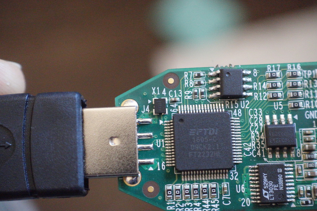
The Lattice iCEstick allows rapid prototyping of the iCE40 FPGA family and has an easy to use USB thumb drive form factor.
The device incorporates FTDI’s FT2232H multipurpose USB to UART/FIFO IC to allow writing the fpga bitstream to flash.
And while flashing the device is easy - it is not immediately obvious how to communicate with the fpga after programming it.
One option is to use a Bus-pirate which connects to the development box using USB and presents a UART interface. This makes it possible to use a serial/terminal program to communicate with the Bus-pirate and to configure it to issue SPI commands to the fpga using the fpga’s gpio.
However, it is frustrating to resort to using another device - when the Icestick already has an on-board USB controller!
One feature of the FT2232H is that it contains not one, but two high speed USB to multipurpose UART/FIFO channels. And the Icestick board designers thoughtfully wired up the second channel to one of the fpga IO banks.
So it should be possible to appropriate the second channel for SPI communication with the fpga.
Can FT2223H Channel-A be used for both programming and communicating?
Before looking at using the FT2223H’s second channel, I wondered if it was possible to use the FT2232H first channel (Channel A) for flash programming as well as communicating with the fpga.
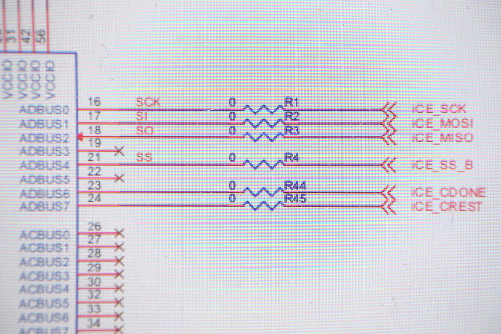
A look at the Icestick schematic from the user manual shows that pin 19 (ADBUS3) is not-connected. According to FTDI documentation it would ordinarily be used for the SPI chip-select. Instead the Icestick board designers chose to appropriate pin 21 - the first GPIO output for CS.
This means that the programmer must manually toggle the chip-select instead of having the FT2223H hardware do it whenever a write is made. However the advantage is that it becomes possible to use different GPIO pins for different chip-selects to support multiplexing different ICs which would open the possibility of multiplexing the fpga.
Unfortunately the schematic also reveals that the only other connected FT2223H GPIO pins available are dedicated to non-GPIO fpga functionality - to implement fpga reset (ICE_CREST)and for signalling the finish of configuration loading (ICE_CDONE). Without any other pins - we must instead consider using Channel B instead.
Using Channel B of the FT2223H
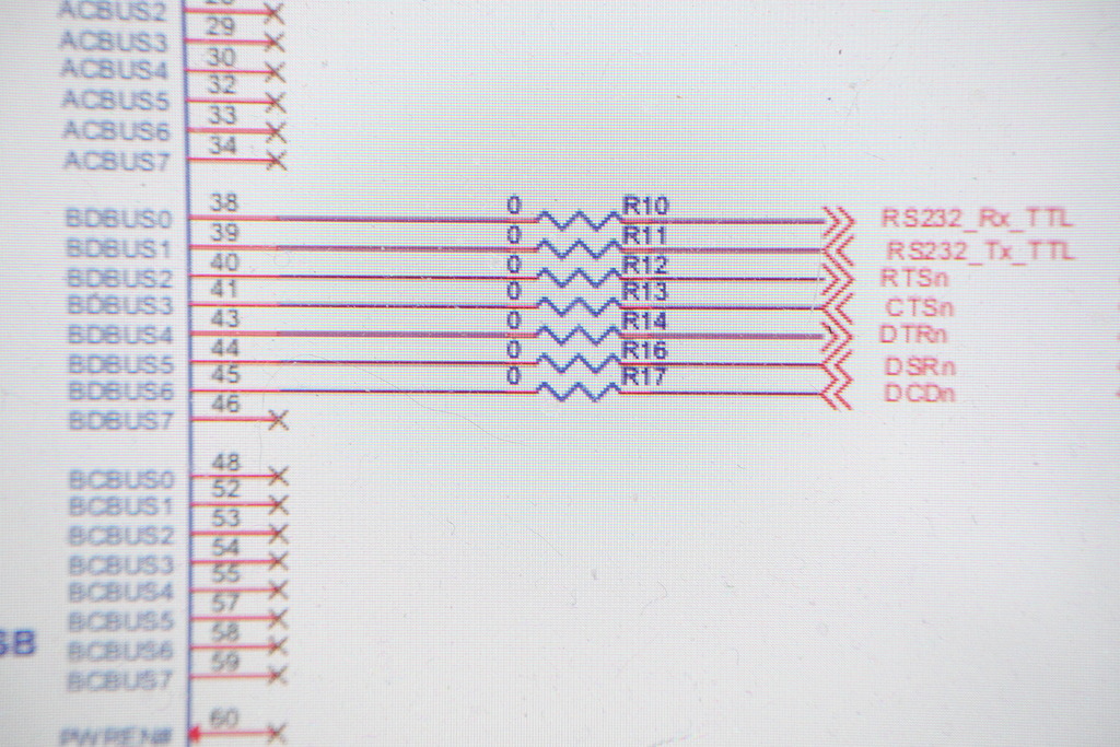
The Icestick user mannual shows the FT2223H Channel B output connected to bank 3 of the fpga. The pin names follow a uart convention (rx/tx ttl etc) but that shouldn’t matter so long as we can put the FT2223H in SPI rather than uart mode.
The first step is to write some simple verilog to connect the expected input pins up to the board LEDs. This should make it possible to try programmatically controlling the FT2223H and toggling the fpga inputs while observing the LEDs to confirm behavior.
Programming the FT2223H using libftdi
For programming the FT2232H I used the FTDI’s libftdi USB library on linux. As well reading FTDI’s documentation, Clifford Wolf’s Icestrom flash programmer iceprog.c provided a jump-start for some of the C code.
The main thing is to put the ftdi device into MPSSE mode instead of uart mode. This allows it to speak many different protocols such as SPI as well as I2C, and more.
  if (ftdi_set_bitmode(&ftdic, 0xff, BITMODE_MPSSE) < 0) {
    fprintf(stderr, "Failed set BITMODE_MPSSE on iCE FTDI USB device.\n");
    error();
  }
After some experimentation, I was able to control the gpio pins of the FTDI and see the expected LEDs light up. Trying some serial writes also showed activity on the sclk and miso LEDs as data was piped across the fpga pins.
The following IO mappings were confirmed as the synthesis contraints.
# identifier    fpga pin, uart name,  ftdi pin,     spi
set_io gpio_l2  1 #       dcd         45,   us6     gpio-l2
set_io gpio_l1  2 #       dsr         44,   us5     gpio-l1
set_io gpio_l0  3 #       dtr         43,   us4     gpio-l0     # use as cs
set_io cs       4 #       ctsn        41,   us3     cs          # ignore
set_io miso     7 #       rtsn        40,   us2     sclk
set_io mosi     8 #       tx ttl,     39,   us1     miso
set_io sclk     9 #       rx ttl,     38,   us0     mosi
FPGA Verilog code for slave SPI
The next step was to implement the Verilog code for the SPI slave. My SPI slave code follows the example code at fpga4fun which handles the system and SPI clock domain crossing.
The Verilog SPI target is a simple command processor. It takes a single byte - either 0xcc or 0xdd and turns a LED on and off in response,
  always @(posedge clk)
    begin
      if(byte_received)
        case (byte_data_received)
          8'hcc:
            led1 <= 1;
          8'hdd:
            led1 <= 0;
      endcase
    end
libftdi C code for driving the FT2232H
The following C excerpt shows the code used to drive the FT2232H to send the SPI commands from the development laptop.
   // assert CS - active low
    set_gpio(0, 1, 1);

    if(led_value == 1)
      data[0] = 0xcc;
    else if(led_value == 0)
      data[0] = 0xdd;

    // write
    send_spi( data, 1 );

    // deassert CS
    set_gpio(1, 1, 1);
Success! We can now successfully control the Icestick on-board LED, over the same USB connection that we used to program the on-board flash.
working but rough example code here.