Zeners (part 5)
Changing the circuit resistor dividers
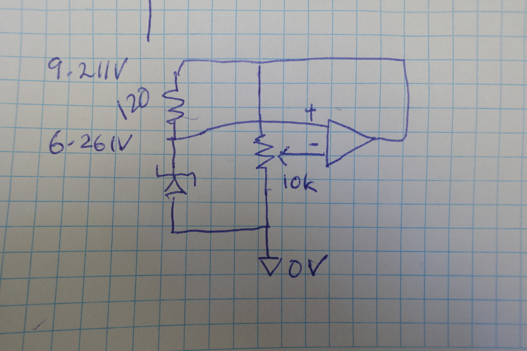
The old divider used a Vishay S-series 120ohm resistor, and Vishay 10k trimpot to indirectly set current across the zener, by varying the voltage on the inverting op-amp input.
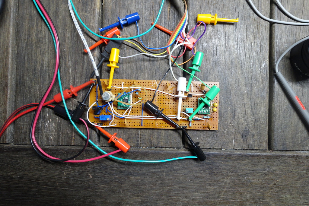
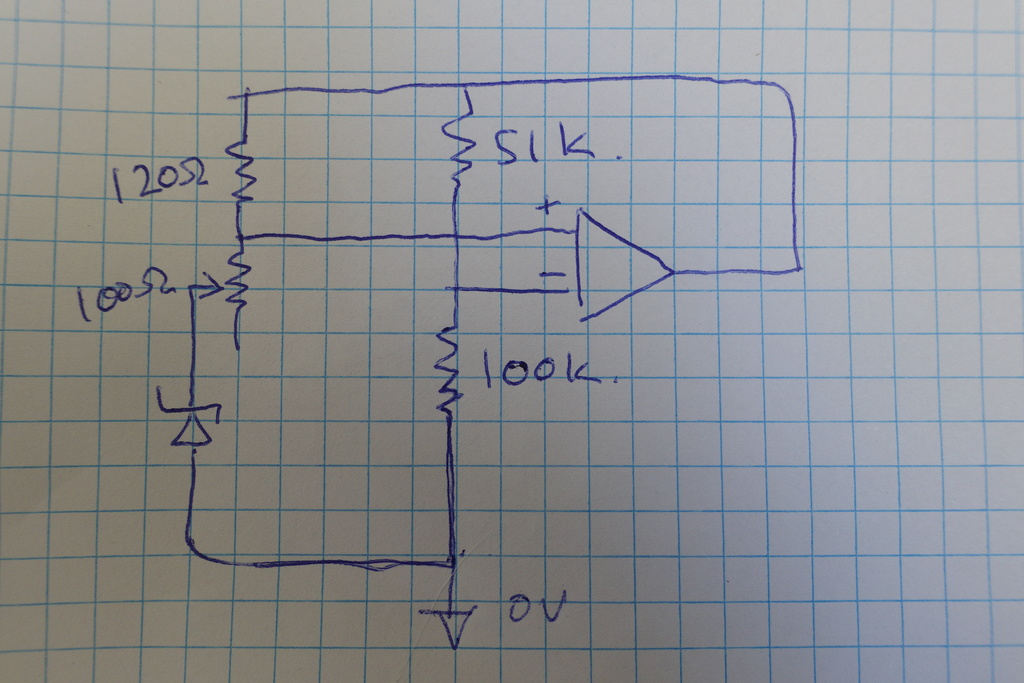
New divider circuit
After seeing how sensitive the 10k pot was to thermal effects, it is useful to investigate if a fixed-resistor divider can improve performance.
The new circuit places the 120ohm resistor in series with a Bourns 100ohm trimmer as current limit for the Zener. And a cheap ebay 1/4watt resistor pair (51k/100k) is used for the inverting op-amp input.
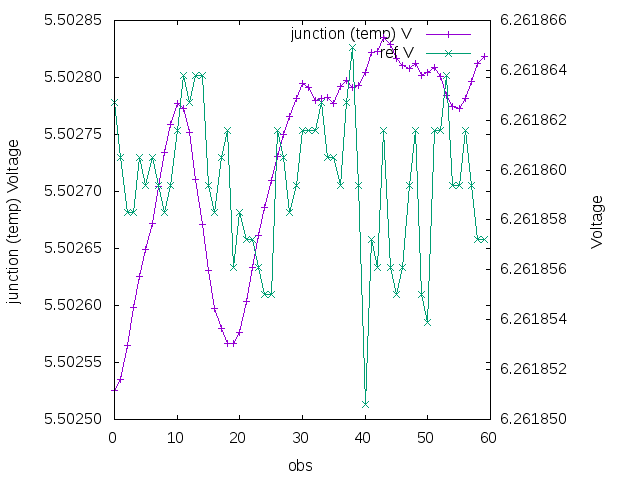
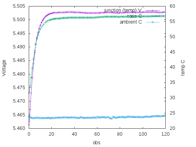
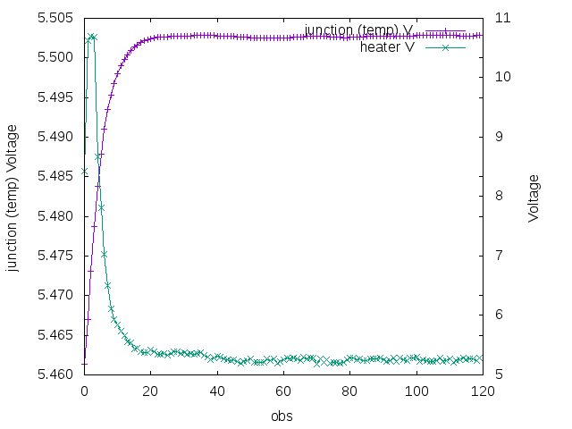
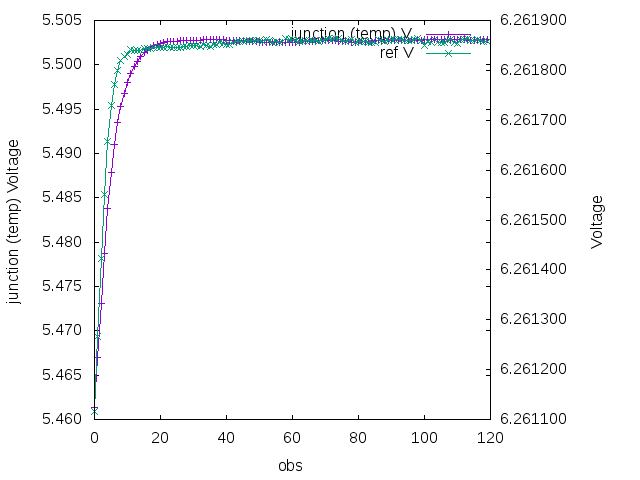
Data
After tuning current to balance tempco, the circuit appears more stable - even in spite of the low specs of the resistor divider
The junction temperature, and regulation loop converge faster and with no excursions!
And there is no weird secondary spiral around the tempco vertex!
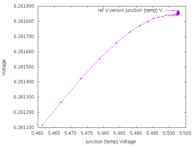
Apart from one outlier obs, all reference voltages are within a 10uV range