Zeners (part 2)
Following from, part-1
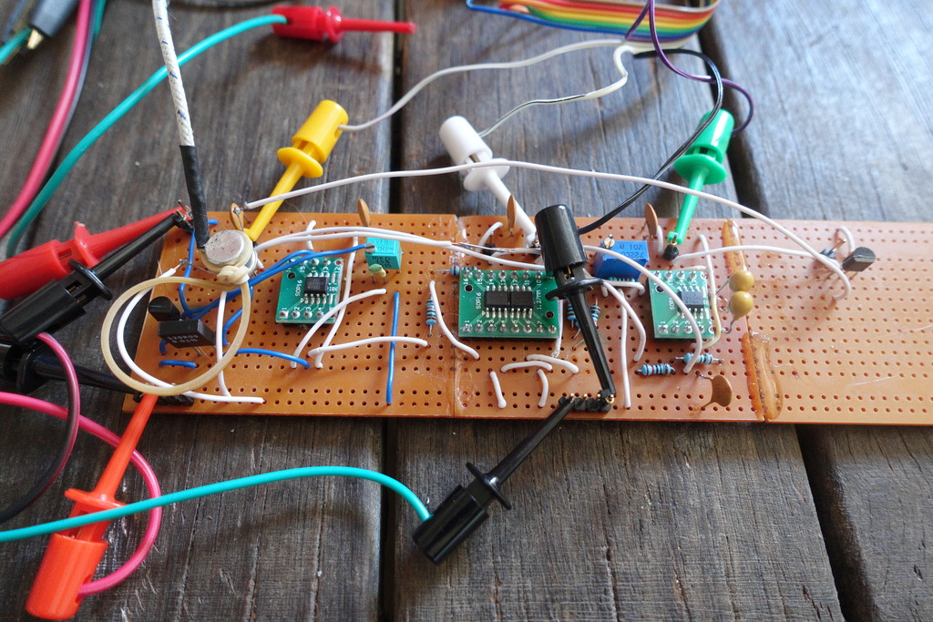
Current adjustment to trim tempco balance is done by manual binary search.
The procedure involves letting the unit cool, applying power and noting the direction of the output voltage as it heats. With some experimentation it is possible to dial in the reference voltage so that voltage initially increases and then dips slightly as temperature converges on the regulation setpoint.
Test data
The measurement time is approximately 20 minutes. Interval is 10 seconds.
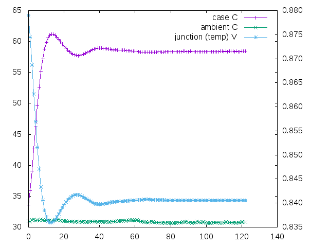
Plot showing ambient temperature, junction temperature voltage, and case temperature looks similar to part-1
Plot of the output-reference voltage and on-die junction temperature, shows regulation working properly
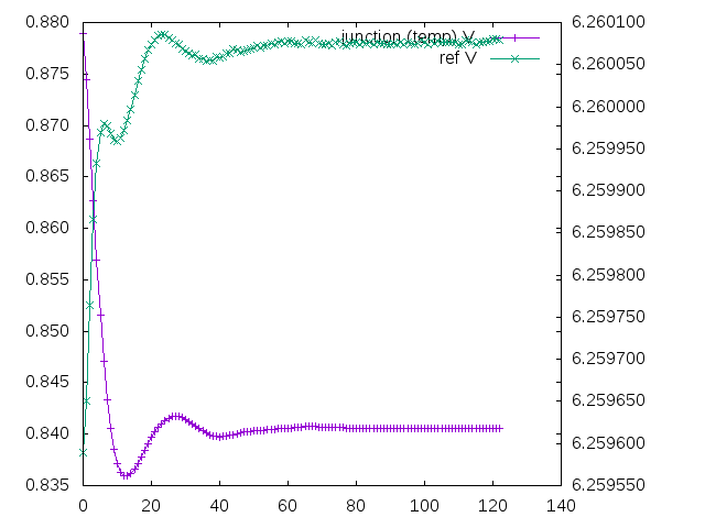
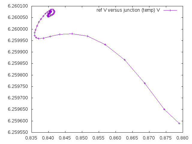
The plot of output-reference voltage versus junction temperature is interesting.
The lhs represents area of higher temperature, and the rhs lower temperature. At startup, the temperature rises and the voltage increases. At a certain temperature the tempco (mV/C) of the forward biased zener is balanced by the tempco of the reversed biased zener, and a local vertex is reached. After a small retracement, there appears to be another secondary affect and curve. The trace eventually converges on the regulation temperature/voltage.
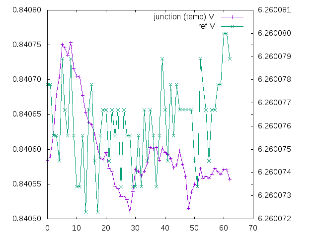
Skipping the first startup observations, provides a higher resolution view on the y axis. The plot shows output voltage varying by 8uV over the course of approximately 15 minutes.
Conditions involve an open room, exposed breadboard, high-ambient temperatures over 30C, circulating air currents, and 7 digit values from the 6.5digit rated data-acquisition unit. Additionally the circuit uses only two precision resistors - the resistors for the op-amps are inexpensive 1/4watt and not tempco rated.