Zeners (part 3)
A simpler circuit
Following from, part-2
After some more thinking, I realized the subtracting op-amp that provides the voltage-drop of the forward-biased zener was unnecessary.
Instead, the reversed-biased zener voltage-drop is the inverse of the forward-biased zener when current is adjusted for tempco balance.
So, after accounting for the reversed zener orientation (from 0.8 to 5.4V), the second zener’s voltage-drop could be used as sense for the temperature regulation loop.
The payoff is a simpler design that eliminates two op-amps.
More test data
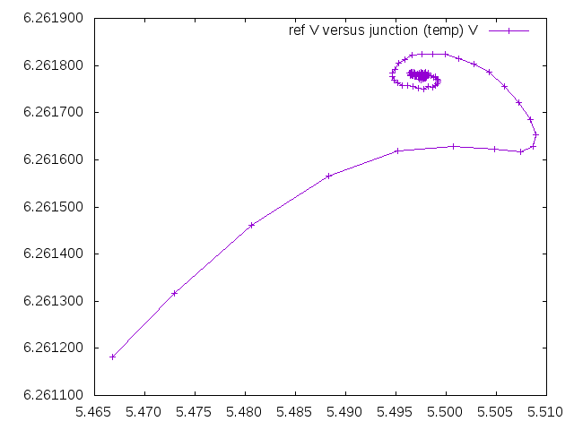
Plot of a cold start. The operating temperature setpoint has been more finely adjusted to be closer to the balanced tempco vertex.
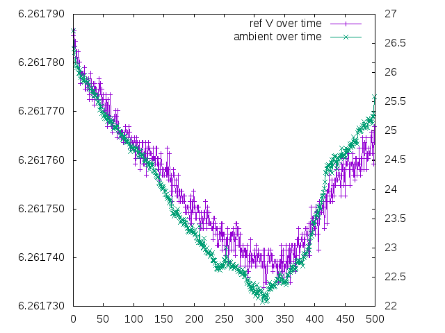
A plot of a longer run over the course of about 18 hours. Output is stronly correlated with ambient temperature. Since the on-die temperature is now regulated to a high degree - suspicion must be on other board components.
The linear relationship is clear when voltage change is plotted directly against ambient temperature. The output variation is around 40uV over 4 degrees.
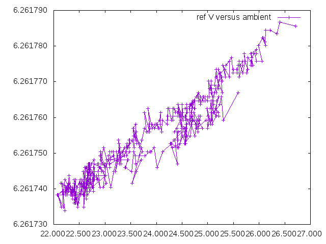
40uV / 4C = 10uV/C, 10uV / 6.26V = 1.6ppm/C
The op-27 op-amps are rated at 0.2uV/C and probably do not contribute a lot to the variation.
However the Vishay trimpots are rated to +-10ppm/C.
Since these are needed for setting current and temperature, it is not clear how much further improvement is possible without entirely ovenizing the board.